
Position Sensors.
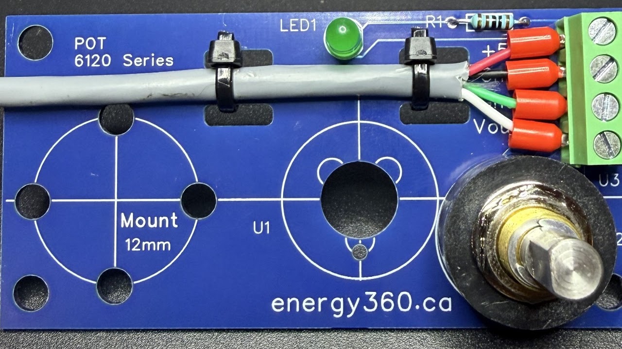
Give each motor a clear position signal. The Energy360 sensor board keeps the potentiometer connection, indicator and cable secured in a compact assembly with two mounting orientations.
Feedback that stays connected.
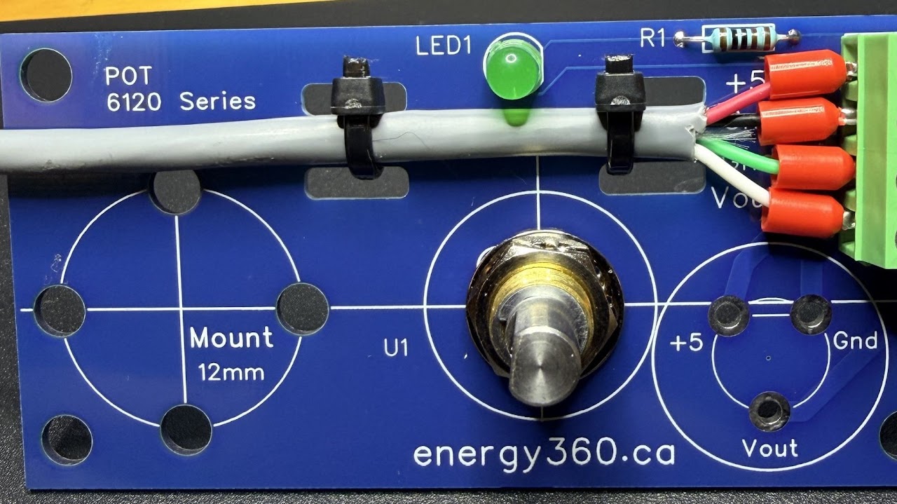
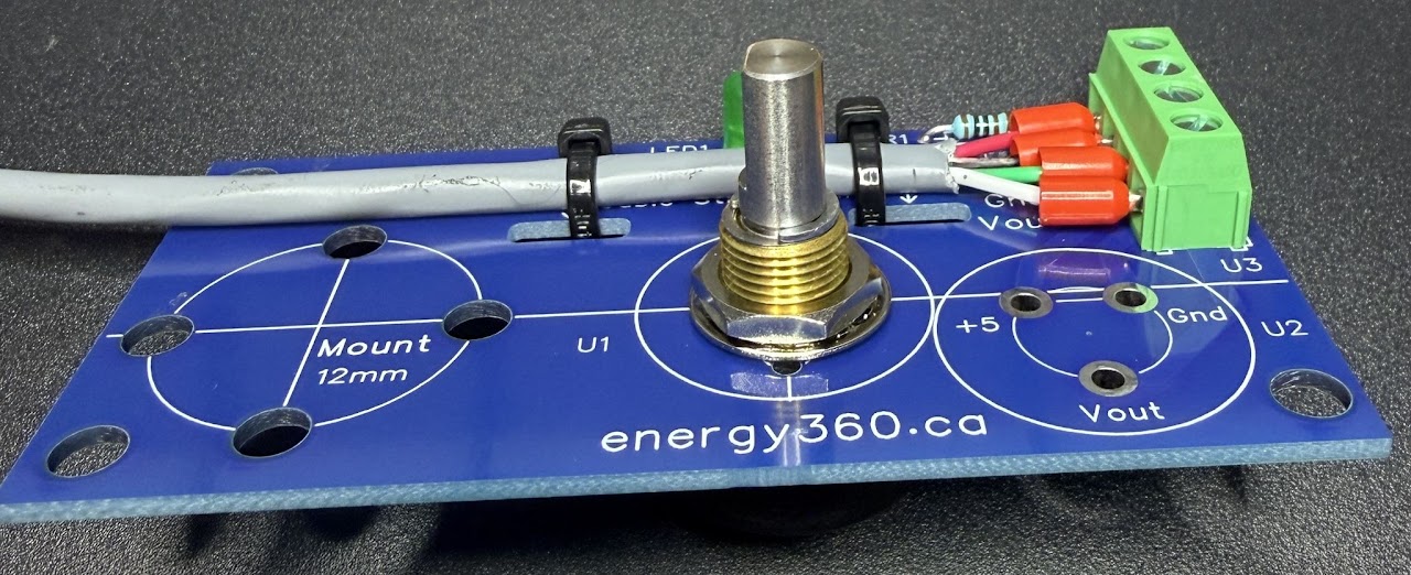
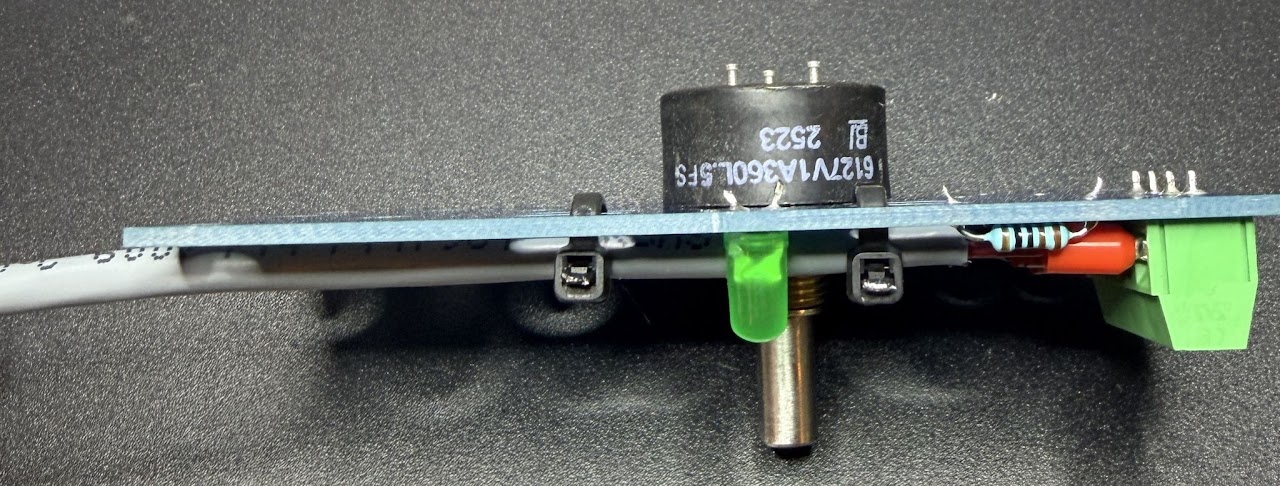
Each motor needs one position sensor. The board gives the sensor a consistent mounting and wiring path, with a power LED to help check the connection, a captured wire terminal and cable strain relief.
Multiple isolated mounting points let you choose a layout that fits the mechanics of your rig.
- One position sensor for each motor
- Power LED for a visual wiring check
- Captured wire terminal connector
- Cable strain relief
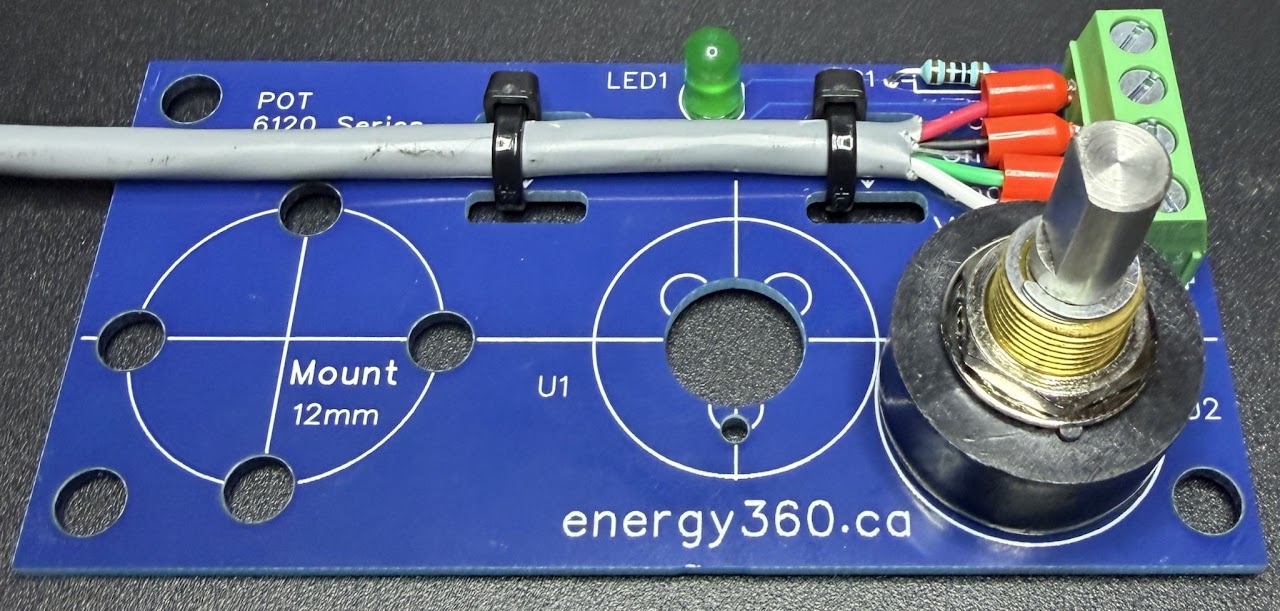
- Position A and Position B potentiometer locations
- Multiple isolated mounting points
Position A.
The potentiometer is soldered directly into the board. This layout avoids separate connector wires between the sensor and PCB.
Choose the board orientation and mount that suit your linkage.
Position B.
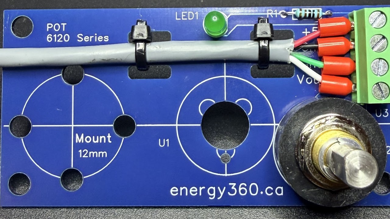
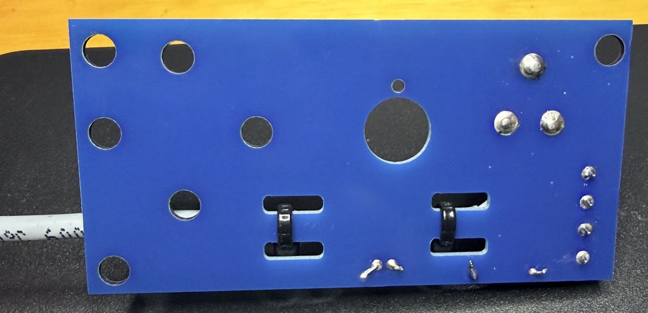
The potentiometer mounts through the board. In this configuration, three wires are soldered from the potentiometer to the PCB.
This gives you another mounting arrangement when the rig geometry calls for it.
Order position sensors.
Tell us how many motors you have, which sensor orientation fits your rig, and your preferred mounting arrangement.
Build your orderQuestions? energy360.ca@gmail.com